Build Your Own Transparent Potentiometer: A Hands-On Learning Tool
Introduction
Potentiometers are everywhere in electronics—from volume knobs to light dimmers—yet their inner workings can seem mysterious to beginners. This DIY project, inspired by [DiscoLapy]'s creation, pulls back the curtain by giving you a fully functional, see-through potentiometer that you assemble yourself. By building it, you'll intuitively grasp how varying resistance controls current in a circuit. Whether you're a teacher, a hobbyist, or a curious learner, this guide walks you through every step. Let's get started!

What You Need
- 3D-printed base and knob (STL files provided; or craft from thick cardboard and a bottle cap)
- Paper (cardstock works best) for the resistive track
- Soft graphite pencil (6B or 8B) to draw the resistive trace
- Metal contacts: two small paper clips or brass fasteners for the ends, and a thin metal strip or wire for the wiper
- Short wires with alligator clips for connecting to a test circuit
- LED and 330Ω resistor (optional, for demonstration)
- Multimeter (optional, for precise resistance measurement)
- Scissors, ruler, craft knife
- Glue or double-sided tape
Step-by-Step Assembly
Step 1: Print or Craft the Mechanical Parts
Start with the base and knob. If you have a 3D printer, download the STL files from the project page (search for DIY transparent potentiometer) and print them in PLA. The base is a flat disc with a central hole and a raised circular track; the knob is a smaller disc with a notch for the wiper. No printer? Cut a 5 cm circle from sturdy cardboard for the base, punch a hole in the center, and use a bottle cap or a 3 cm cardboard disc as the knob. Ensure the knob rotates freely on a small screw or wooden dowel through the center hole.
Step 2: Prepare the Resistive Paper Track
The secret sauce is a graphite trace on paper. Cut a rectangular strip of cardstock about 4 cm × 2 cm—this will be your variable resistor. On one side, use a soft pencil to evenly shade a thick rectangular band from one short edge to the other. Go over it several times to get a dense, shiny graphite layer. The resistance will be roughly 10–50 kΩ depending on the pencil pressure. For consistency, test with a multimeter: the darker and more uniform the coating, the lower the resistance. Trim the paper so the graphite band is about 1 cm wide, leaving clean paper edges at the ends for contacts.
Step 3: Attach the Paper Track to the Base
Place the base in front of you. Apply a thin line of glue or double-sided tape around the raised outer rim of the base (or the outer edge if flat). Carefully lay the paper track graphite-side up along this rim, pressing it down firmly. The track should form a ¾-circle arc, with the two ends of the graphite band positioned at two points about 30° apart—these will be your fixed terminals. Leave the middle of the arc (where the wiper will travel) free from adhesive so the knob's wiper can glide over the graphite.
Step 4: Install the Fixed Contacts
Take two small paper clips and straighten them partially to create L-shaped metal strips. Insert one through a small hole at each end of the graphite track (pierce the paper and base if needed) so that the metal touches the graphite. Bend the other side flat against the base and secure with tape. These are your terminal A and terminal B—the ends of the resistive element. If using brass fasteners, push them through both paper and base and spread the prongs on the underside.
Step 5: Add the Wiper to the Knob
Now for the moving part—the wiper that slides along the graphite. Take a thin strip of springy metal (e.g., a 1 cm × 0.5 cm piece cut from a tin can lid, or a bent paper clip). Sand the tip to remove any coating. Glue or press this strip into the notch on the underside of your knob so that it sticks out perpendicular to the knob's surface. When the knob is placed on the base, the wiper should make gentle contact with the graphite track. Trim the wiper length so it contacts roughly the middle of the track arc. This wiper becomes terminal C.
Step 6: Assemble Knob and Wiper Contact
Push a screw or wooden dowel through the center hole of the base, then through the knob. Secure from below with a nut or a drop of glue, but allow the knob to rotate freely. Rotate the knob to test: the wiper should sweep over the graphite band from one fixed contact to the other without snagging. If it lifts off, bend it down slightly; if it scrapes too hard, shorten it or sand the tip.
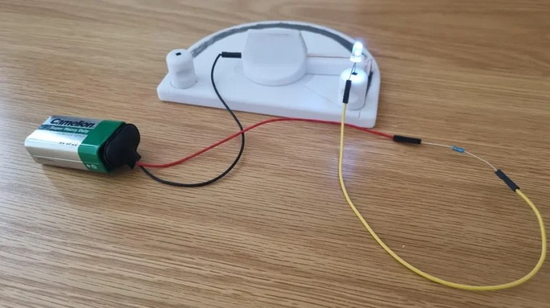
Step 7: Wire It Up and Test
Clip wires to your three terminals: two from the fixed contacts (A and B), and one from the wiper (C). For a quick test, make a simple circuit: connect a 9V battery, an LED with a 330Ω resistor in series, and your potentiometer. Connect the battery positive to terminal A, the LED+resistor to terminal C, and terminal B back to battery negative. When you rotate the knob, the LED should smoothly brighten and dim. If it doesn't, check your graphite trace continuity with a multimeter—you should see resistance change between A-C and B-C as you turn.
Tips for Success
- Use a soft pencil (6B or 8B) for the graphite layer. Harder pencils (H series) contain more clay and produce less conductive traces.
- Even pressure is key. Shade in one direction, then perpendicular, to avoid gaps. A uniform layer gives predictable resistance values.
- Test each step with a multimeter to catch problems early. Between fixed terminals A and B, you should see a constant resistance (for example, 30 kΩ). Between A and wiper (C), the resistance should vary smoothly from near 0 to the full value as you turn.
- If the LED flickers, the wiper may be bouncing. Try a thicker or more flexible metal strip to maintain constant contact.
- Experiment with different trace shapes (wide vs. narrow) to see how geometry affects resistance range.
- This is a teaching tool, not a precision device. Expect resistance variations; that's part of the learning!
- Label the terminals (A, B, C) directly on the base with a marker so students can follow the circuit.
Now you have a fully operational potentiometer you built yourself—and a crystal-clear mental model of how variable resistors work. Use it to experiment, demonstrate Ohm's law, or even as a makeshift dimmer for a small light. Happy building!
Related Discussions